TDEMI devices set new standards with their multi-channel APD measurement function and disturbance rating capabilities
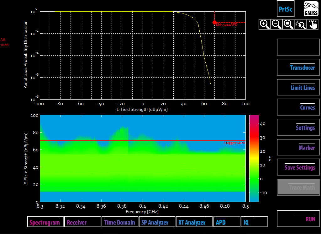
According to CISPR 16-1-1, APD measurements are currently specified for the frequency range above 1 GHz. However, there is a growing demand to extend this functionality allowing for APD measurements to be performed even below 1GHz. APD measurements institute a means to determine statistical distribution for defined amplitude intervals, revealing the probability of exceeding a particular level.
The parallel architecture for signals processing utilized in TDEMI devices facilitate reducing APD measurement duration, which are typically quite time-consuming. The TDEMI ULTRA allows for APD measurements at every frequency point, supporting bandwidths of up to 171.5 MHz.
|
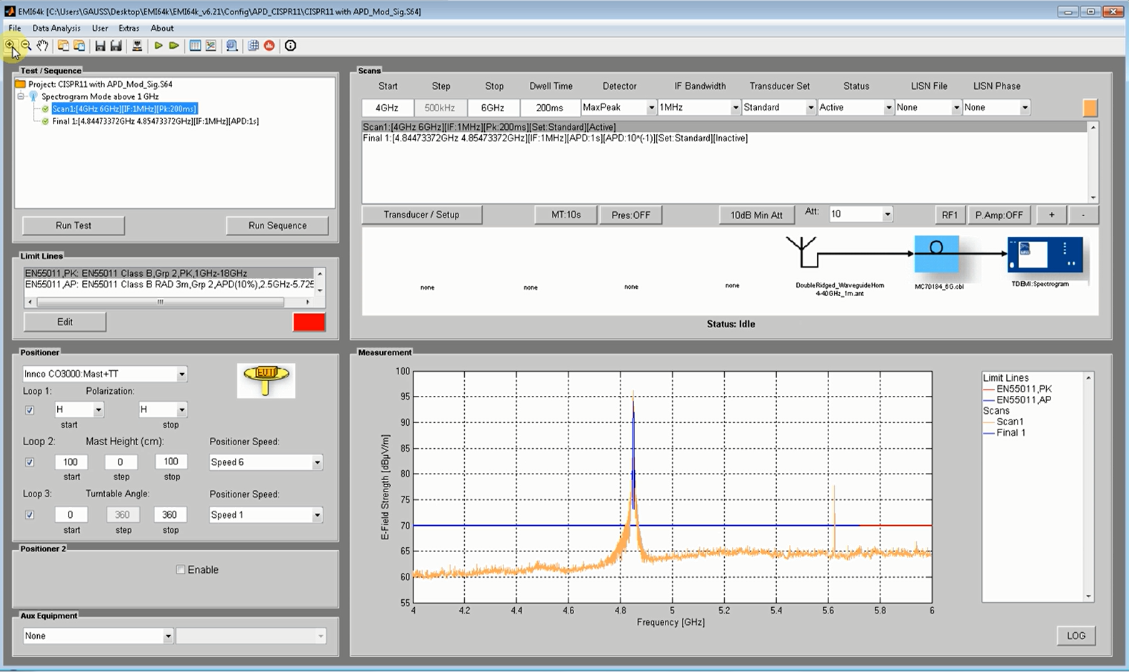
The maximum APD measurement bandwidth for the TDEMI S series is 225MHz. The ability to measure at several thousand frequency points simultaneously significantly improves the performance of APD measurements establishing an efficient way of performing measurements across large frequency ranges for numerous applications. The TDEMI series devices are real-time receivers with wide ranging capabilities. EMC measurements in compliance with all common standards for radio measurements and digital demodulation of radio channels are possible using these receivers. The recent feature extension adding APD measurement functionality to the TDEMI device family also operates in full compliance with requirements laid out by its respective standards and for example enables automated EMC tests in accordance with CISPR 11. |
|
Real time measurements such as pre-scanning with peak detector can be performed fully automated and at high measurement speeds with the EMI64k automation software. The procedure is reduced to just a few seconds due to the high measurement reliability. A complete characterization of the unit under test is attainable by recording the emissions at all frequency points across all angular positions. Points at which, for example the limit line for ISM devices is exceeded, can then be transferred to a marker table. Both the exact position and the level are documented. |
|