Radio Frequency & Microwave Technology
For our ultra high-speed analog-to-digital converter systems, manufactured in impeadance controlled multi-layer technology with up to 12 layers, special high-performance analog and mechanical components are needed. Such high performance systems are assembled in mechanically precise manufactured enclosures machined from a single piece of aluminium thus providing an excellent heat dissipation and best long term stability over the years of operation.
The TDEMI Measurement Systems in the upper GHz range use analog circuits with excellent RF performance for the front-end.
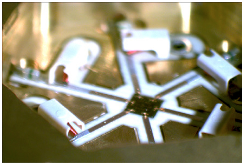
Such circuits have been developed and optimized especially for the application in EMC measurements. In Fig. 40 a part of a multi-channel switch for the frequency range up to 26.5 GHz is shown. A special thin-film substrate and bare die monolithic integrated circuits enable highest performance. The complete mounted circuits are assembled in enclosures with highly mechanical precision made of gold-plated brass providing excellent RF characteristics. In the upper frequency range filter, mixer and switches are used which exhibit excellent RF performance, e.g. the pre-selection up to 26.5 GHz uses filters with a loss of less than 1 dB. Filters with low dispersion allow excellent impulse response for broadband signals.
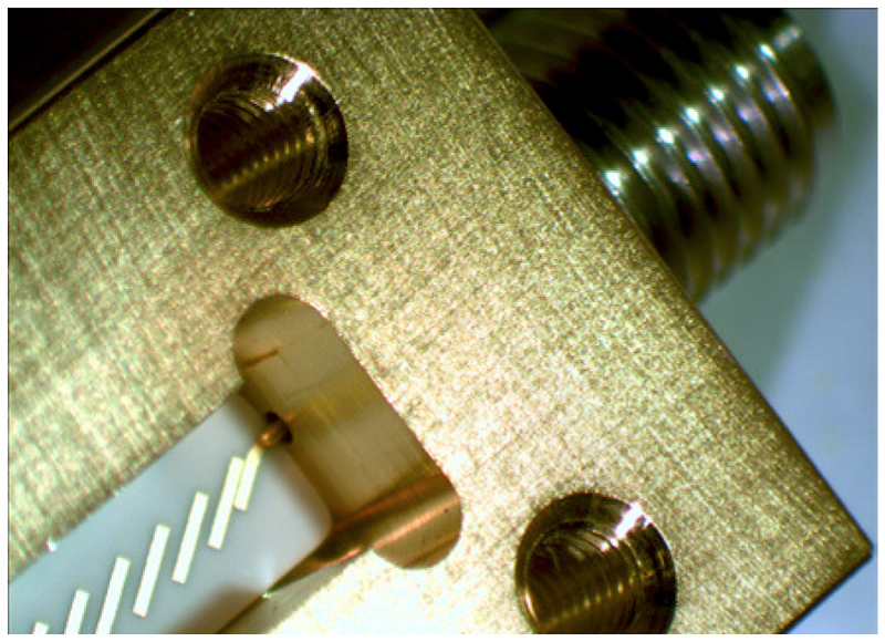
Fig. 41 shows a bandpass filter. For the development of such circuits very powerful simulation tools are used. The filters are manufactured on special thin-film ceramic substrates which are assembled in gold-plated precision enclosures finally.
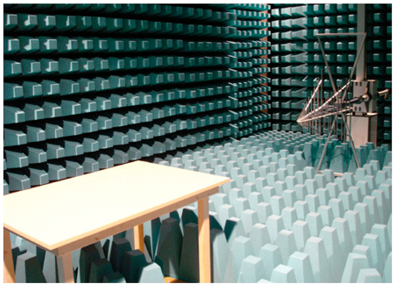
Emission measurements in the frequency range can be carried out on open area test sites (OATS) or in anechoic chambers. Fig. 42 shows a fully anechoic chamber for testing of frequencies up to 20 GHz. To compensate the missing tips of the absorbers the room is completely cladded with special ferrite tiles.